Category 5
Installing Cabling and HardwareCategory 5 installation will not exceed the 100 meter (328 foot) standard. All data cables are to be installed in a point to point fashion, no splices, cross connects, or patching of any kind. The data will be terminated at the distribution point, (computer room/computer closet) using category 5, 568B 110-type connection patch panels with eight (8) pin RJ45 connectors or ports in the front. Typically a horizontal wire manager is installed for each patch panel. The patch panels will be clearly labeled with the same number and or letter as the station jack. |
|
CAT-5:
Category 5 Ethernet cable. Most frequently used LAN cable these days. Up to 100 MBit/sec, up to 100m (300 ft) long. CAT-3 is an older version for up to 10 MBit/sec. Newer versions, for even higher speed, are labled CAT-5e or CAT-6.
ategory 5 describes network cabling that consists of four twisted pairs of copper wire terminated by RJ45 connectors. Cat-5 cabling supports frequencies up to 100 MHz and speeds up to 1000 Mbps. It can be used for ATM, token ring, 1000Base-T, 100Base-T, and 10Base-T networking.
Computers hooked up to LAN s are connected using Cat-5 cables, so if you're on a LAN, most likely the cable running out of the back of your PC is Category 5.
Cat-5 is based on the EIA/TIA 568 Commercial Building Telecommunications Wiring Standard developed by the Electronics Industries Association as requested by the Computer Communications Industry Association in 1985.
| 1) | The RJ-45 plugs are normally made for either solid conductors or stranded conductors. It is very important to be sure that the plug that you use matches the conductor type. It is extremely difficult to tell the difference between the two by looking at them. When you buy these plugs, be sure to categorize, and store them carefully. Using the wrong type can cause intermittent problems. |
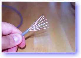
| 2) | Ordinarily, it would be taboo to untwist the pairs of any category 5 cable. The one exception to this rule is when crimping on RJ-45 plugs. It would be impossible to insert the wires into the channels without first untwisting and straightening them. Be sure not to extend the un-twisting, past the skin point. If you do it properly, you will wind up with no more than 1/2" of untwisted conductors (up to 1/2" of untwist meets the cat 5 specification) |
| 3) | If the completed assembly does not pass continuity, you may have a problem in one, or both ends. First try giving each end another crimp. If that does not work, then carefully examine each end. Are the wires in the proper order? Do all of the wires fully extend to the end of the connector? Are all of the pins pushed down fully. Cut off the suspected bad connector, and re-terminate it. If you still have a problem, then repeat the process, this time giving more scrutiny to the end that was not replaced. |
| 4) | It is good to be prepared to make your own patch cables. There may be many instances where you may fall short on supply, and making a cable will surely get you out of a jam. However, there comes a point where the practicality curve will lead you to factory made cables. Making several cables can be very labor intense. Factory made cables typically have better tolerances, and consequently have better quality than field made cables |
| 568-B Wiring (RJ-45) | . |
568-A Wiring (RJ-45) | |||||||||||||||||||||||||||||||||||||||||||||||||||||||||||||||||||||||||||||||||||||||||||||||||||||||||||||||||||||||||||||||||||||||||||||||||||||||||||||||||||||||||||||||||||||||||||||||||||||||||||||||||||||||
|
|
|
| ||||||||||||||||||||||||||||||||||||||||||||||||||||||||||||||||||||||||||||||||||||||||||||||||||||||||||||||||||||||||||||||||||||||||||||||||||||||||||||||||||||||||||||||||||||||||||||||||||||||||||||||||||||||
|
Notes for wiring diagrams above: 1. For patch cables, 568-B wiring is by far, the most common
method. | |||||||||||||||||||||||||||||||||||||||||||||||||||||||||||||||||||||||||||||||||||||||||||||||||||||||||||||||||||||||||||||||||||||||||||||||||||||||||||||||||||||||||||||||||||||||||||||||||||||||||||||||||||||||||
Patch Cable Assembly Instructions |
 |
1) Skin off the cable jacket approximately 1" or slightly
more. 2) Un-twist each pair, and straighten each wire between the fingers. 3) Place the wires in the order of one of the two diagrams shown above (568B or 568A). Bring all of the wires together, until they touch. 4) At this point, recheck the wiring sequence with the diagram. 5) Optional: Make a mark on the wires at 1/2" from the end of the cable jacket. |
8) Insert the wires into the connector (pins facing up). | 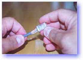 | |
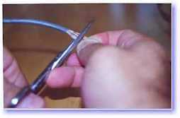 |
6) Hold the grouped (and sorted) wires together tightly,
between the thumb, and the forefinger. 7) Cut all of the wires at a perfect 90 degree angle from the cable at 1/2" from the end of the cable jacket. This is a very critical step. If the wires are not cut straight, they may not all make contact. We suggest using a pair of scissors for this purpose. |
9) Push moderately hard to assure that all of the wires have reached the end of the connector. Be sure that the cable jacket goes into the back of the connector by about 3/16". | 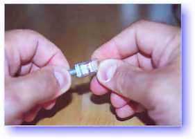 | |
 |
7B) Conductors should be at a straight 90 degree angle, and be 1/2" long, prior to insertion into the connector. | 9) Place the connector into a crimp tool, and squeeze hard
so that the handle reaches it's full swing. |
 | |
| 10) Repeat the process on the other
end. For a straight through cable, use the same wiring. For a "crossover"
cable, wire one end 568A, and the other end 568B. 11) Use a cable tester to test for proper continuity. |
||||
INTRODUCTION. The purpose of this article is to show you how to make the two kinds of cables which can be used to network two or more computers together to form quick and simple home or small office local area networks (LANs). These instructions can also be used to make patch cables for networks with more complex infrastructure wiring.
The two most common unshielded twisted-pair (UTP) network standards are the10 Mhz 10BASE-T Ethernet and the 100Mhz 100BASE-TX Fast Ethernet. The 100BASE-TX standard is quickly becoming the predominant LAN standard. If you are starting from scratch, to build a small home or office network, this is clearly the standard you should choose. This article will show you how to make cables which will work with both standards.
|
|
LANS SIMPLIFIED. A LAN can be as simple as two computers, each having a network interface card (NIC) or network adapter and running network software, connected together with a crossover cable.
The next step up would be a network consisting of three or more computers and a hub. Each of the computers is plugged into the hub with a straight-thru cable (the crossover function is performed by the hub).
There are several classifications of cable used for twisted-pair networks. I'll skip right over them and state that I use and recommend Category 5 (or CAT 5) cable for all new installations. Likewise, there are several fire code classifications for the outer insulation of CAT 5 cable. I use CMR cable, or "riser cable," for most of the wiring I do. You should also be aware of CMP or plenum cable (a plenum is used to distribute air in a building). You may be required by local, state or national codes to use the more expensive plenum-jacketed cable if it runs through suspended ceilings, ducts, or other areas, if they are used to circulate air or act as an air passage from one room to another. If in doubt, use plenum. CMR cable is generally acceptable for all applications not requiring plenum cable.
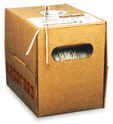 CAT 5 wire is
available in reel-in-box packaging. This is very handy for pulling the wire
without putting twists in it. Without this kind of package or a cable reel
stand, pulling wire is a two-person job. Before the advent of the
reel-in-box, we used to put a reel of wire on a broom handle to pull it.
One person would hold the broom handle and the other would pull and measure the
cable. You will produce a tangled mess, if you pull the wire off the end
of the reel.
CAT 5 wire is
available in reel-in-box packaging. This is very handy for pulling the wire
without putting twists in it. Without this kind of package or a cable reel
stand, pulling wire is a two-person job. Before the advent of the
reel-in-box, we used to put a reel of wire on a broom handle to pull it.
One person would hold the broom handle and the other would pull and measure the
cable. You will produce a tangled mess, if you pull the wire off the end
of the reel.
Stranded wire patch cables are often specified for cable segments running from a wall jack to a PC and for patch panels. They are more flexible than solid core wire. However, the rational for using it is that the constant flexing of patch cables may wear-out solid core cable--break it. I don't think this is a real concern in the average small network. For example, I have one solid core cable going to my work bench. It has probably flexed and average person's lifetime of flexes from the many many times I have connected customer computers to my network. Also, stranded cable is susceptible to degradation from moisture infiltration, may use an alternate color code, and should not be used for cables longer than 3 Meters (about 10 feet).
Most of the wiring I do simply connects computers directly to other computers or hubs. Solid core cable is quite suitable for this purpose and for many home and small business networks. I find it also quite acceptable for use as patch cables. You might consider a stranded wire patch cable if you have a notebook computer you are constantly moving around.
CAT 5 cable has four twisted pairs of wire for a total of eight individually insulated wires. Each pair is color coded with one wire having a solid color (blue, orange, green, or brown) twisted around a second wire with a white background and a stripe of the same color. The solid colors may have a white stripe in some cables. Cable colors are commonly described using the background color followed by the color of the stripe; e.g., white-orange is a cable with a white background and an orange stripe.
 CONNECTORS. The straight through and cross-over patch
cables discussed in this article are terminated with CAT 5 RJ-45 modular
plugs. RJ-45 plugs are similar to those you'll see on the end of your
telephone cable except they have eight versus four or six contacts on the end of
the plug and they are about twice as big. Make sure they are rated for CAT
5 wiring. (RJ means "Registered Jack"). Also, there are RJ-45 plugs
designed for both solid core wire and stranded wire. Others are designed
specifically for one kind of wire or the other. Be sure you buy
plugs appropriate for the wire you are going to use. I use plugs designed
to accommodate both kinds of wire.
CONNECTORS. The straight through and cross-over patch
cables discussed in this article are terminated with CAT 5 RJ-45 modular
plugs. RJ-45 plugs are similar to those you'll see on the end of your
telephone cable except they have eight versus four or six contacts on the end of
the plug and they are about twice as big. Make sure they are rated for CAT
5 wiring. (RJ means "Registered Jack"). Also, there are RJ-45 plugs
designed for both solid core wire and stranded wire. Others are designed
specifically for one kind of wire or the other. Be sure you buy
plugs appropriate for the wire you are going to use. I use plugs designed
to accommodate both kinds of wire.
Modular Plug Crimp Tool. You will need a modular crimp tool. This one is very similar to the one I have been using for many years for all kinds of telephone cable work and it works just fine for Ethernet cables. You don't need a lot of bells and whistles, just a tool which will securely crimp RJ-45 connectors. This one is made by Eclipse Enterprises, Inc. Even though the crimper has cutters which can be used to cut the cable and individual wires, and possibly stripping the outer jacket, I find that the following tools are better for stripping and cutting the cable...
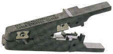 Universal UTP
Stripping Tool (Eclipse). I recently bought one of these tools and it
works slick, and it makes a much neater cut. I recommend that you purchase
one if you will be making many cables.
Universal UTP
Stripping Tool (Eclipse). I recently bought one of these tools and it
works slick, and it makes a much neater cut. I recommend that you purchase
one if you will be making many cables.
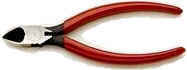 Diagonal Cutters ("4
to 6"). It is easier to use diagonal cutters ("diags" or "dikes") to cut
the cable off at the reel and to fine tune the cable ends during assembly.
Also, if you don't have a stripper, you can strip the cable by using a small
knife (X-acto, utility, etc.) to carefully slice the outer jacket
longitudinally and use the diags to cut it off around the circumference.
Diagonal Cutters ("4
to 6"). It is easier to use diagonal cutters ("diags" or "dikes") to cut
the cable off at the reel and to fine tune the cable ends during assembly.
Also, if you don't have a stripper, you can strip the cable by using a small
knife (X-acto, utility, etc.) to carefully slice the outer jacket
longitudinally and use the diags to cut it off around the circumference.
The 10BASE-T and 100BASE-TX Ethernets consist of two transmission lines. Each transmission line is a pair of twisted wires. One pair receives data signals and the other pair transmits data signals. A balanced line driver or transmitter is at one end of one of these lines and a line receiver is at the other end. A (much) simplified schematic for one of these lines and its transmitter and receiver follow:
Pulses of energy travel down the transmission line at about the speed of light (186,000 miles/second). The principal components of one of these pulses of energy is the voltage potential between wires and current flowing near the surface of the wires. This energy can also be considered as residing in the magnetic field which surrounds the wires and the electric field between the wires. In other words, an electromagnetic wave which is guided by, and travels down the wires.
The main concern is the transient magnetic fields which surrounds the wires and the magnetic fields generated externally by the other transmission lines in the cable, other network cables, electric motors, fluorescent lights, telephone and electric lines, lightning, etc. This is known as noise. Magnetic fields induce their own pulses in a transmission line which may literally bury the Ethernet pulses, the conveyor of the information being sent down the line.
The twisted-pair Ethernet employs two principle means for combating noise. The first is the use of balanced transmitters and receivers. A signal pulse actually consists of two simultaneous pulses relative to ground: a negative pulse on one line and a positive pulse on the other. The receiver detects the total difference between these two pulses. Since a pulse of noise (shown in red in the diagram) usually produces pulses of the same polarity on both lines one pulse is essentially canceled by out the other at the receiver. Also, the magnetic field surrounding one wire from a signal pulse is a mirror of the one on the other wire. At a very short distance from the two wires the magnetic fields are opposite and have a tendency to cancel the effect of each other out. This reduces the line's impact on the other pair of wires and the rest of the world.
The second and the primary means of reducing cross-talk--the term cross-talk came from the ability to (over) hear conversations on other lines on your phone--between the pairs in the cable, is the double helix configuration produced by twisting the wires together. This configuration produces symmetrical (identical) noise signals in each wire. Ideally, their difference, as detected at the receiver, is zero. In actuality it is much reduced.
|
Let's start with simple pin-out diagrams of the two types of UTP Ethernet cables and watch how committees can make a can of worms out of them. Here are the diagrams:
Note that the TX (transmitter) pins are connected to corresponding RX (receiver) pins, plus to plus and minus to minus. And that you must use a cossover cable to connect units with identical interfaces. If you use a straight-through cable, one of the two units must, in effect, perform the cross-over function. Two wire color-code standards apply: EIA/TIA 568A and EIA/TIA 568B. The codes are commonly depicted with RJ-45 jacks as follows: | ||||||||||
|
|
| |||||||||
| If we apply the
568A color code and show all eight wires, our pin-out looks like this:
Note that pins 4, 5, 7, and 8 and the blue and brown pairs are not used in either standard. Quite contrary to what you may read elsewhere, these pins and wires are not used or required to implement 100BASE-TX duplexing--they are just plain wasted. However, the actual cables are not physically that simple. In the diagrams, the orange pair of wires are not adjacent. The blue pair is upside-down. The right ends match RJ-45 jacks and the left ends do not. If, for example, we invert the left side of the 568A "straight"-thru cable to match a 568A jack--put one 180° twist in the entire cable from end-to-end--and twist together and rearrange the appropriate pairs, we get the following can-of-worms:
Keeping the above principles in mind, we can simplify the diagram for a 568A straight-thru cable by untwisting the wires, except the 180° twist in the entire cable, and bending the ends upward. Likewise, if we exchange the green and orange pairs in the 568A diagram we will get a simplified diagram for a 568B straight-thru cable. If we cross the green and orange pairs in the 568A diagram we will arrive at a simplified diagram for a crossover cable. All three are shown below.
| ||||||||||
 This further emphasizes, I hope, the
importance of the word "twist" in making network cables which will
work. You cannot use an flat-untwisted telephone cable for a network
cable. Furthermore, you must use a pair of twisted wires to connect
a set of transmitter pins to their corresponding receiver pins. You
cannot use a wire from one pair and another wire from a different
pair.
This further emphasizes, I hope, the
importance of the word "twist" in making network cables which will
work. You cannot use an flat-untwisted telephone cable for a network
cable. Furthermore, you must use a pair of twisted wires to connect
a set of transmitter pins to their corresponding receiver pins. You
cannot use a wire from one pair and another wire from a different
pair.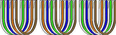
There are only two unique cable ends in the preceding diagrams. They correspond to the 568A and 568B RJ-45 jacks and are shown to the right.
Again, the wires with colored backgrounds may have white stripes and may be denoted that way in diagrams found elsewhere. For example, the green wire may be labeled Green-White--I don't bother. The background color is always specified first.
Now, all you need to remember, to properly configure the cables, are the diagrams for the two cable ends and the following rules:
-
A straight-thru cable has identical ends.
-
A crossover cable has different ends.
It makes no functional difference which standard you use for a straight-thru cable. You can start a crossover cable with either standard as long as the other end is the other standard. It makes no functional difference which end is which. Despite what you may have read elsewhere, a 568A patch cable will work in a network with 568B wiring and 568B patch cable will work in a 568A network. The electrons couldn't care less.
My preference is to use the 568A standard for straight-thru cables and to start crossover cables with a 568A end. That way all I have to remember is the diagram for the 568A end, that a straight-thru cable has two of them, and that the green and orange pairs are swapped at the other end of a crossover cable.
1. Pull the cable off the reel to the desired length and cut. I have a box of cable at one end of my shop and a mark on the floor 10' away. For cable lengths which are a fraction of ten feet, I eye-ball the length as I pull the cable out of the box (also, my feet are about one foot long). For longer cables, I pull it out to the ten foot mark and go back to the box and pull the remaining fraction or another ten feet. If you are pulling cables through walls, a hole in the floor, etc., it easier to attach the RJ-45 plugs after the cable is pulled. The total length of wire segments between a PC and a hub or between two PC's cannot exceed 100 Meters (328 feet or about the length of a football field) for 100BASE-TX and 300 Meters for 10BASE-T.
![]() 2. Strip one end of the cable with the stripper or a
knife and diags. If you are using the stripper, place the cable in the
groove on the blade (left) side of the stripper and align the end of the cable
with the right side of the stripper. This is about right to strip a little
over 1/2" of the jacket off the cable. Turn the stripper about one
turn or so. If you turn it much more, you will probably nick the
wires. The idea is to score the outer jacket, but not go all the way
through. Once scored, you should be able to twist the end of the jacket
loose and pull it off with one hand while holding the rest of the cable with the
other. If you are using a knife and diags, carefully slit the cable for
about an inch or so and neatly trim around the circumference of the cable with
the diags to remove the jacket.
2. Strip one end of the cable with the stripper or a
knife and diags. If you are using the stripper, place the cable in the
groove on the blade (left) side of the stripper and align the end of the cable
with the right side of the stripper. This is about right to strip a little
over 1/2" of the jacket off the cable. Turn the stripper about one
turn or so. If you turn it much more, you will probably nick the
wires. The idea is to score the outer jacket, but not go all the way
through. Once scored, you should be able to twist the end of the jacket
loose and pull it off with one hand while holding the rest of the cable with the
other. If you are using a knife and diags, carefully slit the cable for
about an inch or so and neatly trim around the circumference of the cable with
the diags to remove the jacket.
3. Inspect the wires for nicks. Cut off the end and start over if you see any. You may have to adjust the blade with the screw at the front stripper. Cable diameters and jacket thicknesses vary.
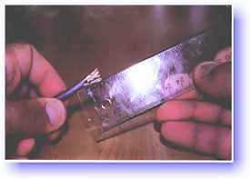
 4. Spread and arrange the pairs roughly in the order
of the desired cable end.
4. Spread and arrange the pairs roughly in the order
of the desired cable end.
 |
5. Untwist the pairs and arrange the wires in the order of the desired cable end. Flatten the end between your thumb and forefinger. Trim the ends of the wires so they are even with one another. It is very important that the unstripped (untwisted) end be slightly less than 1/2" long. If it is longer than 1/2" it will be out-of-spec and susceptible to crosstalk. If it less than slightly less than 1/2" it will not be properly clinched when RJ-45 plug is crimped on.. Flatten again. There should be little or no space between the wires.
 6. Hold the RJ-45 plug with the clip facing down or away from
you. Push the wire firmly into the plug. Now, inspect the darn
thing... before crimping and wasting the plug! Looking through the bottom
of the plug, the wire on the far left side will have a white background.
The wires should alternate light and dark from left to right. The furthest
right wire is brown. The wires should all end evenly at the front of the
plug. The jacket should end just about where you see it in the
diagram--right on the line. Aren't you glad you didn't crimp the plug?
6. Hold the RJ-45 plug with the clip facing down or away from
you. Push the wire firmly into the plug. Now, inspect the darn
thing... before crimping and wasting the plug! Looking through the bottom
of the plug, the wire on the far left side will have a white background.
The wires should alternate light and dark from left to right. The furthest
right wire is brown. The wires should all end evenly at the front of the
plug. The jacket should end just about where you see it in the
diagram--right on the line. Aren't you glad you didn't crimp the plug?
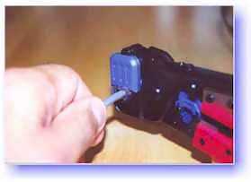
7. Hold the wire near the RJ-45 plug with the clip down and firmly push it into the left side of the front of the crimper (it will only go in one way). Hold the wire in place squeeze the crimper handles quite firmly. This is what will happen:
 |
 |
(Crimp it once.) The crimper pushes two plungers down on the RJ-45 plug. One forces what amounts to a cleverly designed plastic plug/wedge onto the cable jacket and very firmly clinches it. The other seats the "pins," each with two teeth at its end, through the insulation and into the conductors of their respective wires.
8. Test the crimp... If done properly an average person will not be able to pull the plug off the cable with his or her bare hands. And that quite simply, besides lower cost, is the primary advantage of twisted-pair cables over the older thinwire, coaxial cables. In fact, I would say the RJ-45 and ease of its installation is the main reason coaxial cable is no longer widely used for small Ethernets. But, don't pull that hard on the plug. It could stretch the cable and change its characteristics. Look at the side of the plug and see if it looks like the diagram and give it a fairly firm tug to make sure it is crimped well.
9. Prepare the other end of the cable so it has the desired end and crimp.
10. If both ends of the cable are within reach, hold them next to each other and with RJ-45 clips facing away. Look through the bottom of the plugs. If the plugs are wired correctly, and they are identical, it is a straight-thru cable. If they are wired correctly and they are different, it is a crossover cable.
11. If you have an operational network, test the cable. Copy some large files.
12. If the cable doesn't work, inspect the ends again and make sure you have the right cable and that it is plugged into the correct units for the type of cable. Try power-cycling (cold booting) the involved computers.
13. If you have many straight-thru cables and a crossover cable in your system, you should consider labeling the crossover cable or using a different colored cable for the crossover cable so you don't mix them up. I do not recommend implementing the crossover function, as recommended elsewhere, with two RJ-45 jacks, appropriately wired back to back, and two straight-thru cables. This method costs noticeably more, introduces more than the necessary number of components and connections, increases the complexity and time of assembly, and decreases reliability.
1. Try to avoid running cables parallel to power cables.
2. Do not bend cables to less than four times the diameter of the cable.
3. If you bundle a group of cables together with cable ties (zip ties), do not over-cinch them. It's okay to snug them together firmly; but don't tighten them so much that you deform the cables.
4. Keep cables away from devices which can introduce noise into them. Here's a short list: copy machines, electric heaters, speakers, printers, TV sets, fluorescent lights, copiers, welding machines, microwave ovens, telephones, fans, elevators, motors, electric ovens, dryers, washing machines, and shop equipment.
5. Avoid stretching UTP cables (tention when pulling cables should not exceed 25 LBS).
6. Do not run UTP cable outside of a building. It presents a very dangerous lightning hazard!
7. Do not use a stapler to secure UTP cables. Use telephone wire/RJ6 coaxial wire hangers which are available at most hardware stores.
| ||||||||||||||||||||||||||||||||||||||||||||||||||||||||
|
Category 5 Installation, Do's and Don'ts | ||||||||||||||||||||||||||||||||||||||||||||||||||||||||
| ||||||||||||||||||||||||||||||||||||||||||||||||||||||||